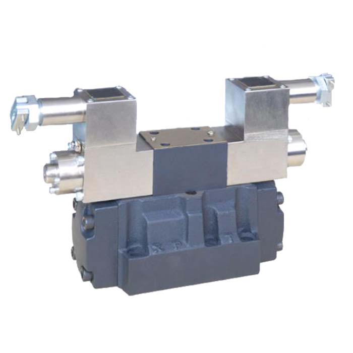
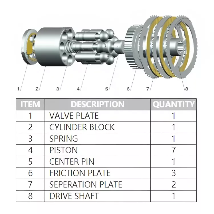
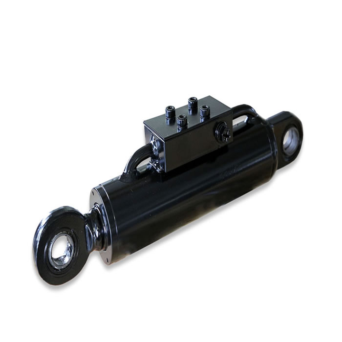
hydraulic system for pressure mounted hydraulic motor

(1) Host functional structure
During the assembly of machine parts, there is often a pressing process for bushing parts. Pressing processes are often arranged between assembly lines. In order to adapt to the high-speed and high-efficiency process rhythm of assembly line, press-mounting hydraulic press is usually required to have high speed (generally up to 10 m/min), light pressure (generally at 10-50 kN) and reliable energy-saving performance. However, common hydraulic press is universal, but its speed and efficiency often can not meet the requirements. The hydraulic press is mainly used for pressing and assembling connecting rod pins of assembly line of engine for agricultural vehicles. The Hydraulic System of speed-up cylinder supplied by fixed displacement pump has met the above requirements and achieved satisfactory results in production.
(2) Hydraulic system and its working principle
Figure 2-33 shows the schematic diagram of the hydraulic system of the connecting rod pin press. The actuator of the system is the acceleration Hydraulic Cylinder 13, which is composed of a large cylinder (piston cylinder) and a small cylinder (piston cylinder) (the piston is fixed to the cylinder head of the large cylinder). The piston rod of the large cylinder acts as the cylinder cylinder of the small cylinder simultaneously, thus forming three cavities A, B and C with different working areas. Under the same input flow condition, different working speeds can be obtained by changing the working chamber of the acceleration cylinder and the working mechanism (pressure head) driven by the acceleration cylinder. Therefore, the system uses a fixed hydraulic pump 1 to supply oil. Relief valve 3 is used to limit the maximum operating pressure of the system for safety protection.
The work cycle completed by the hydraulic system is shown in Fig. 2-34. The downward and upward movement of the head driven by the hydraulic cylinder is controlled by the three-position four-way solenoid change-over valve 4. The hydraulic pump can also be unloaded by the M-type neutral function of the valve 4. The system adopts the mode of opening pump and holding pressure (holding pressure can be remotely regulated by relief valve 10 connected by remote control port of pilot relief valve 1l); Pressure release is achieved by a hydraulic control check valve 14 with an unloading valve center. Relief valve 7 acts as backpressure. The supply pressure of the hydraulic pump can be observed by the pressure gauge 6 through the pressure gauge switch 5 and the back pressure of the cylinder by the pressure gauge 9.
The oil flow path of the system under each operating condition is as follows.
1) Fast downward (near workpiece) energization of solenoid 1YA causes the change-over valve 4 to switch to the left position. The pressure oil of hydraulic pump 1 enters cavity A of accelerator cylinder 13 through the change-over valve 4. Because of the small area of this cavity, the piston rod drives the pressure head to go down quickly and approach the workpiece. At the same time, the secondary oil tank 15 above the cylinder fills the fluid through cavity B of 14-way cylinder of hydraulic control check valve. The oil in cylinder C chamber overcomes the back pressure of relief valve 7 and is discharged back to tank through valve 4.
2) Pressure retaining When the workpiece is in place, the hydraulic pump continues to supply oil to cavities A and B of the cylinder. The system maintains pressure to keep the workpiece in pressed state. Pressure retaining value is set by relief valves 9 and 11. During pressure retaining process, excess oil in the cylinder overflows back to the main tank through valve 3 high pressure.
3) After pressure relief and fast return (up) pressure retaining, solenoids 1YA and 3YA are cut off, 2YA are energized, valves 4 and 12 are switched to right and left positions respectively. Pressure oil of hydraulic pump 1 opens the pressure retaining chamber of hydraulic control check valve 14 to cylinder to release pressure. After reaching a certain pressure value, the pressure oil of hydraulic pump enters the C chamber of cylinder via valve 4 and valve 8, and drives the pressure head to go up quickly. The oil of A chamber is discharged directly to the main oil tank 16 via valve 4. The oil in chamber B is returned to the secondary tank 15 via the pilot-opened hydraulic check valve 14 and the excess oil is returned to the main tank via the overflow chamber of the secondary tank.
4) When the stop head returns to its original position, the solenoid 2YA is powered off, the valve 4 returns to its neutral position, the accelerator cylinder stops, and the hydraulic pump unloads to complete a work cycle.
(3) Technical characteristics
1) The head is driven by the acceleration cylinder, with the same speed of advance and retreat; With a fixed displacement pump oil source, the flow rate of the hydraulic pump is determined at a slow-forward speed (which is also the fast-forward flow rate of the cylinder). The flow specification and driving power of the hydraulic pump are greatly reduced compared with those of a conventional hydraulic cylinder system (see Table 2-11). The area of the three oil chambers is determined by load and ratio of speed to speed (the piston diameter of the cylinder is determined by the compressive loading force and the selected hydraulic system pressure; the piston diameter is determined by the ratio of speed to speed; and the piston rod diameter is determined by the same rate of speed to speed).
2) Elimination of throttling elements, no excess flow during operation of the system, thus improving volumetric efficiency; The working pressure of the hydraulic pump always follows the change of the load pressure, and the flow rate of the pipeline does not increase when the cylinder rises and falls rapidly. Except in the holding pressure stage, the pressure loss is small (ignoring the loss of the pipeline). Therefore, reactive power loss and heating in operation of the system are reduced, and energy-saving effect is achieved.
3) The fast and slow speed changes are obtained by changing the effective action area of the accelerator cylinder in the lifting cycle and the function of back Pressure Valve. As a result, the impact and vibration during speed change are small and the operation is smooth and high.
(4) Technical parameters (see Table 2-11)
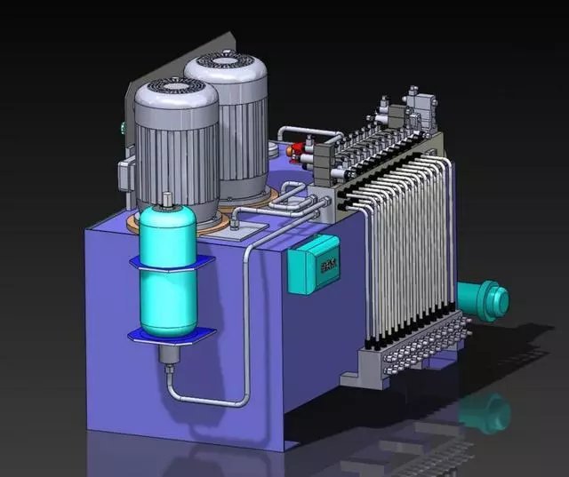
Table 2-11 Technical parameters of hydraulic system for connecting rod pin press
Project
parameter
Company
Host
Pressing force
40
KN
Fast rising and lowering speed
7.2
M/min
Press-fit speed
1.5
Hydraulic system
Working pressure
7
MPa
Maximum flow rate
9.6 (45.8 for normal cylinders)
L/min
Hydraulic cylinder
Piston diameter
90
Mm
Piston rod diameter
80
Piston diameter
40

