Hydraulic valves failure reason analysis and countermeasures
Hydraulic valve is the most used components in the Hydraulic System, its function is to control the flow direction of the fluid, pressure, flow, in order to meet the executive element of the power required by the direction, force (or torque), speed requirements, so that the entire hydraulic system can be coordinated according to the requirements of the work. So when the hydraulic valve failure, the stability of the hydraulic system, precision and reliability have a great impact, and even cause the system can not work at all.
Failure analysis of hydraulic valves can not be simply equated with the failure of general mechanical parts analysis, it also belongs to the hydraulic components of their own factors. In this paper, Xing Di source of machinery on the hydraulic valve failure of several common phenomena to discuss, in order to do in the management of hydraulic equipment to prevent problems before they occur.
1,mechanical failure:
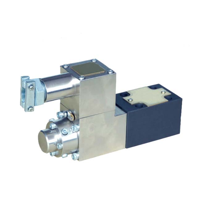
Explosion isolation proportional directly operated pressure-relief valve
1.1 wear and tear
Hydraulic valve spool, valve sleeve, valve body and other mechanical parts of the movement between the vice, in the use of friction, making the size and shape of the parts and surface quality changes and failure.
Solenoid valve spool wear or deformation, will make the valve leakage and make the efficiency decline, and dirt easy to enter the gap or deformation, so that the spool to produce mechanical obstruction phenomenon. If the spool and the valve hole clearance is too large, will produce pressure impact. Pressure reducing valve pilot valve wear will make the valve work unstable, or even can not regulate pressure. Relief valve pilot cone valve (or pilot small ball valve) at the wear and tear and sealing is not tight, can not be normal pressure regulation. One-way throttle (speed control) valve check valve part of the wear, sealing is not tight, part of the oil flow will flow through the check valve, affecting the sensitivity of the speed control.
1.2 Fatigue
Working under long-term variable load, the spring in the hydraulic valve will be caused by fatigue spring softening, spring length shortening or the whole broken; spool, valve seat will also be fatigue, cracks, spalling or other damage. These may cause the valve to fail. Spring fatigue or breakage on the relief valve main slide valve or pilot valve will make the system pressure fail to meet the requirements. The spring of the directional valve is too soft or short, which will affect the working position of the spool and normal reset, making the system can not work properly.
1.3 Deformation
Hydraulic valve parts in the processing of residual stress and the use of the process of external load stress exceeds the yield strength of the parts material, the parts produce deformation, can not complete the normal function and failure. Relief valve spool bending deformation or spring deformation, will make the spool movement is not flexible, resulting in system pressure instability. Unloading valve spool bending deformation will make the spool action is slow, so that the system from the unloading to the working pressure or working pressure to unloading the conversion process is slow. Bending deformation of the spool of the directional valve will make the valve reversing action difficult to carry out normally. Note that improper assembly may also cause deformation of parts, for example: directional valve assembly screws tightened too tightly and caused by the deformation of the valve body may make the spool jamming.
1.4 Corrosion
Hydraulic oil mixed with too much water or acidic substances, after a long time of use, will corrode the relevant parts in the hydraulic valve, so that the loss of due accuracy and failure.
2, hydraulic clamping:
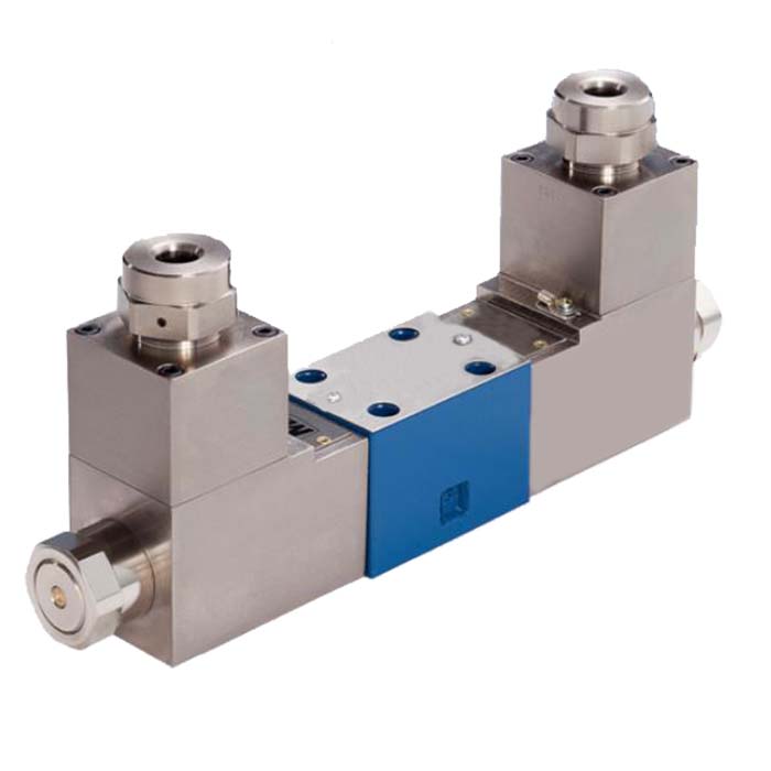
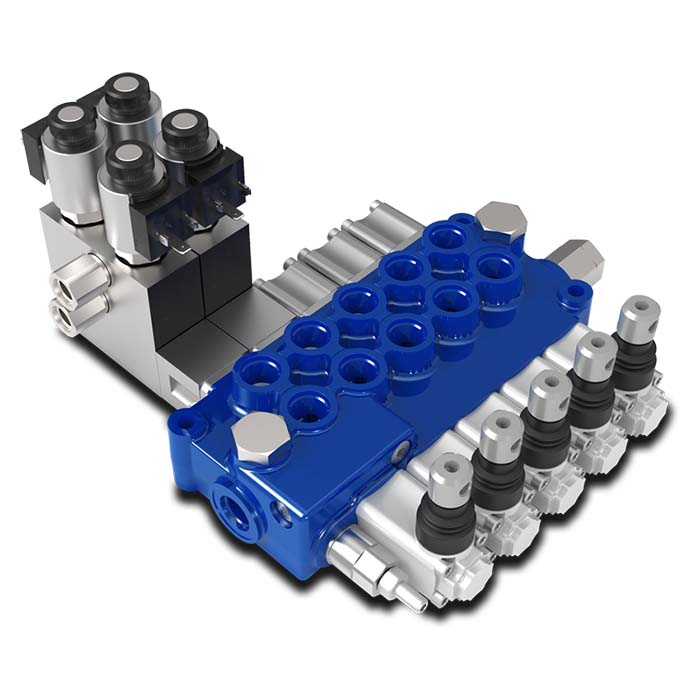
Explosion isolation proportional directional control valve
2.1 hydraulic clamping reasons
Pressure fluid flow through the hydraulic valve cylindrical slide valve structure, acting on the spool of the radial unbalance force on the spool stuck, known as “hydraulic clamping”. Hydraulic system to produce “hydraulic clamping” is due to the slide valve geometry errors and coaxial changes in the spool to produce radial unbalanced force results.
2.2 Hydraulic clamping hazards
Slight “hydraulic clamping” so that the spool moving friction resistance increases, serious can lead to the control of the system components action lag, so that the hydraulic equipment failure. When the hydraulic clamping resistance is greater than the spool moving force, the spool will be “hydraulically jammed”, can not move. If the movement of the hydraulic spool is driven by electromagnetic force, once the spool is “hydraulically jammed”, the AC solenoid is very easy to damage. “Hydraulic jamming” will accelerate the wear of the slide valve, reducing the service life of the components.
2.3 Hydraulic clamping elimination
Should improve the cleanliness of the hydraulic oil, reduce the chances of particulate contaminants into the spool and valve hole surface. To ensure that the spool and the valve hole with precision. When assembling and installing the slide valve, ensure that the tightening torque, and should be uniformly tightened. Ensure the proper temperature of the hydraulic oil in use to avoid deformation of the spool due to thermal expansion. For the surface of the spool with pressure equalization groove, should pay attention to the pressure equalization groove of the smooth.
3, hydraulic shock:
3.1 hydraulic shock causes
Hydraulic system, due to rapid change of direction or close the oilway, so that the system flow of oil suddenly change direction or stop flowing, and cause a sharp rise in pressure, the formation of a large pressure peak, that is, the hydraulic shock. It can be seen that the main reason for the hydraulic shock is due to the sudden start or stop of the hydraulic components.
3.2 Hydraulic shock hazards
Hydraulic system to produce hydraulic shock, the peak pressure of the fluid is high, sometimes up to 3 ~ 4 times the normal pressure. Therefore, the system's control valves and other hydraulic components, piping, measuring instruments will suffer damage, Pressure Relays, overcurrent relays and other non-normal signals will be issued, resulting in the system can not work properly.
3.3 Prevention of hydraulic shock
Under the premise of ensuring the rhythm of work, try to slow down the speed of direction change. Such as manual reversing, the operation should not be too fast, too violent; for two-stage reversing valve, pilot valve and the main valve should be installed between the throttle or suitable damping, so as to reasonably regulate the main valve reversing speed; single-stage valves can also be added to damping, in order to slow down the valve's reversing speed, to extend the switching time and reduce the hydraulic shock. Cartridge valve control cover should be installed suitable damping. Some hydraulic circuits, due to system reasons will inevitably produce hydraulic shock, should also be taken to install accumulators, strengthen the fixed, hard pipe to hose and other measures to minimize the harm of hydraulic shock on the equipment.
4, the phenomenon of air pockets:
4.1 Causes of air pockets
In the hydraulic system, due to changes in the flow rate of liquid pressure drop caused by the phenomenon of air bubbles called “air pockets”. The reason for air pockets is that when a localized hydraulic system pressure is lower than a specific temperature dissolved in the oil in the air separation of the critical pressure, the original dissolved air in the oil will be a large number of separation out, the formation of bubbles. If the pressure continues to fall, below the saturation vapor pressure of the solution at a specific temperature, the oil boiling and rapid evaporation, resulting in a large number of bubbles, these bubbles mixed in the work of the fluid so that the original pipeline full of or components in the fluid to become intermittent, the formation of the “air pockets”.
4.2 Hazards of air pockets
When the bubble with the oil flow into the high-pressure area, the sudden contraction, some in the high-pressure oil flow under the impact of rapid rupture, recondensation for the liquid, so that the original occupation of the volume reduction and the formation of a “vacuum”, and around the high-pressure oil point of mass to the center of the vacuum to the very fast speed, thus causing the local violent pressure impact; at the same time, the point of mass of the fluid At the same time, the kinetic energy of the oil point is converted into pressure energy, and the pressure and temperature rise sharply here, resulting in violent vibration and strong noise. In the bubble condensation near the surface of the components, repeated pressure impact at high temperature conditions, coupled with the separation of acidic gases in the oil, has a certain corrosive effect, so that the surface material spalling, the formation of small pockmarks and honeycomb, that is, produced cavitation. Cavitation and cavitation make the hydraulic system performance deterioration, reduced reliability.
4.3 Cavitation prevention
Hydraulic equipment to prevent cavitation and cavitation of the main measures to reduce the amount of air in the fluid, pay attention to the system in the pump shaft seal, piping joints sealing situation, the height of the oil level, the return pipe into the tank mouth, etc., to prevent suction air. Pay attention to the oil temperature to prevent the oil from vaporizing at high temperature. The suction line should be large enough and kept free, so that the system oil pressure is higher than the critical pressure of gas-oil separation. Prevent the hydraulic oil mixed with volatile substances and water, so as not to volatilize out in the low-pressure region to form bubbles and become water vapor bubbles.
5. Conclusion:
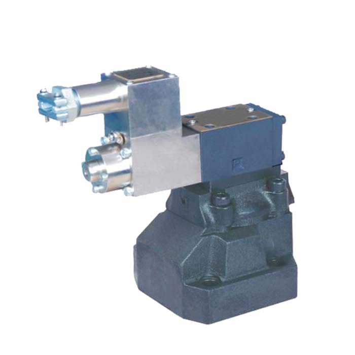
Explosion isolation solenoid check valve
From the above analysis, the mechanical failure of the hydraulic valve in addition to processing and manufacturing factors, mainly related to management. Hydraulic valve as an important component of the hydraulic system, in the implementation of the control task, the structure of its functional parts are all sealed in the valve body or integrated block, it is impossible to directly observe. Often when the system can not work properly, only to attract attention and be resolved. Simply with this approach to make up after the fact is difficult to ensure the normal operation of the system. As a hydraulic equipment managers, only seriously analyze the reasons for the failure of the valve, in order to analyze and solve the problem can be targeted, and can be more pre-judgment, pre-processing, due to the failure of the valve equipment failures nipped in the bud.
Hydraulic valve failure, often not directly from its own first observed, usually reflected in the hydraulic system can not work properly, and the hydraulic system can not work properly and inevitably manifested in the equipment can not work properly. Equipment can not work properly, the reasons are many and varied, especially the high level of automation of metallurgical equipment, often by mechanical, hydraulic, electrical and other factors affect each other, contact, intertwined together and caused. Therefore, the analysis of the problem should be considered as a whole, but if we can pay more attention to the failure of the hydraulic valve, often for the solution of equipment failure to open a breakthrough.

