double acting hydraulic cylinder troubleshooting
1. Fault phenomenon
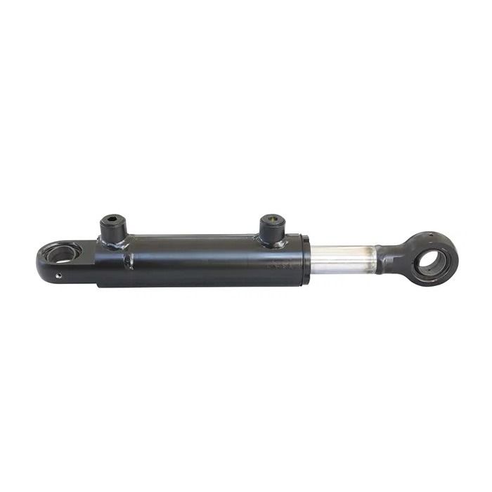
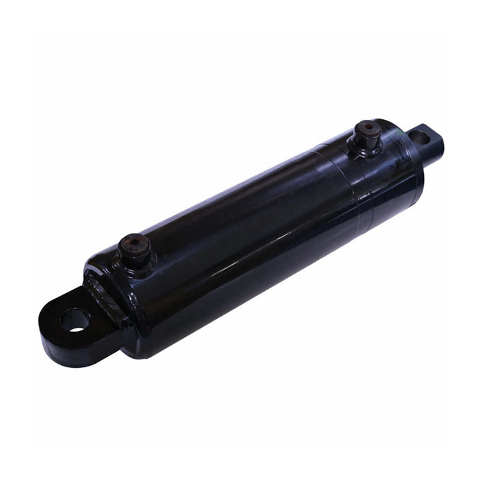
A two-stage sleeve telescopic double-acting Hydraulic Cylinder is selected for a product. The piston and the sleeve adopt a threaded nesting type. The processing technology is the same as that of the piston-type single-acting hydraulic cylinder. The quality is easy to guarantee and the reliability is good, but the structure is complicated. . After a certain lifting operation, it was found that the piston rod was strained and leaked; at the same time, the oil cylinder was blocked, and the first-stage piston rod could not be retracted. In order to avoid more accidents, the multi-stage oil cylinder was dismantled and inspected, and it was found that the guide limit part had plastic deformation, the flat step edge was damaged, and the sharp iron filings scratched the chrome-plated layer of the piston rod, which further damaged the seal. Circulation, causing the leakage of the oil cylinder; at the same time, the back pressure of the oil return is high when the cylinder is retracted with no load, and the pressure loss is large.
2. Cause Analysis
The oil cylinder is analyzed, and the selection of the cylinder diameter and piston rod diameter of the multi-stage telescopic double-acting oil cylinder is too large for the consideration of the white body structure, as shown in Figure R. The primary cylinder diameter and rod diameter are φ200mm and φ190mm, respectively, and the secondary cylinder diameter and rod diameter are φl60mm and φ150mm, respectively. There is only a 5mm gap on each side of each stage of the oil cylinder. Usually, the oil cylinder starts to extend step by step from the largest stage, that is, the φ200mm oil cylinder moves first with the second stage inside it. Only one stage begins to extend; and when retracting, after the smallest stage is fully retracted, the next stage begins to move and retracts into the cylinder step by step. Since the contact surface between each stage of the piston and the guide limit is very small, if the cylinder extends quickly, the piston will collide with the limit, and the long-term collision will cause plastic deformation of the guide limit, resulting in the piston rod hairpin and scratching. Damage to the chrome-plated layer, repeated expansion and contraction of the cylinder will further damage the sealing ring, resulting in jamming and leakage. The first-stage speed ratio of the selected oil cylinder is 10.5, and the second-stage speed ratio is 8.25. When the first stage is extended in place, the same flow enters the second stage, and its extension speed increases. However, the oil cylinder is not designed with a buffer device, which can quickly extend The piston will hit the guide part at the end of the stroke. This part has not been specially treated, and it will fail after a long time. As for the high oil return back pressure when the cylinder is retracted, it is mainly caused by the large speed ratio of the multi-stage cylinder. The same amount of oil enters the rod cavity, and the oil discharge volume of the rodless cavity is expanded by dozens of times. In the system design, Most of them are selected according to the oil supply of the pump, ignoring the increase in flow caused by the speed ratio. The strange phenomenon of increasing the engine throttle or consuming power.
3. countermeasures
Hydraulic Schematic If the cylinder extension speed can be reduced so that it reaches the end of the stroke smoothly, the collision problem can be solved. Therefore, the hydraulic principle is improved and designed, and the principle is shown in Figure S.
When the multi-stage cylinder is extended, the electromagnetic reversing valve 3 is in the right position, the throttle valve 2 firstly adjusts the oil coming from the pump, and the return oil from the rod cavity returns to the fuel tank through the one-way valve of the one-way throttle valve 6. At the same time, the high-pressure oil closes the hydraulic control check valve 4, so that the extension speed of the oil cylinder can be controlled to avoid high-speed impact. When the multi-stage cylinder is retracted, the electromagnetic reversing valve 3 is in the left position, the throttle valve 2 firstly adjusts the oil coming from the pump, and the one-way throttle valve 6 adjusts the flow twice according to the speed requirement, while the high-pressure oil It leads to the control port of the hydraulic control check valve 4. Open the hydraulic control valve to make it flow in the reverse direction. The return oil from the rodless cavity returns to the fuel tank through the hydraulic control valve 4 and the throttle valve 5. The throttle valve 5 can be adjusted Back pressure to prevent the vacuum from being retracted too quickly and causing system vibration and noise in the rodless cavity; the other hydraulic oil discharged from the rodless cavity can be returned to the fuel tank through the T1 port through the electromagnetic reversing valve.

