Understanding Graphical Symbols and Terminology for Directional Valves
Introduction
Hydraulic directional valves are essential components in Hydraulic Systems, controlling the flow and direction of hydraulic fluid. Understanding the graphical symbols used to represent these valves is crucial for designing, troubleshooting, and maintaining hydraulic systems. This article provides a comprehensive overview of the graphical symbols used in hydraulic directional valves, their meanings, and how they are applied in system diagrams.
Graphical Symbols
Squares: Represent the valve body and its positions.
Arrows: Indicate the flow direction of oil.
"T" lines: Represent closed oil circuits.
Dots: Indicate the number of "throughs" or connections.
"P," "A," "B," and "T": Represent the inlet, working, and return ports.
"W": Represents the control mode and reset spring.
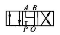
Meaning
"Through": The number of connections between ports.
"Positions": The number of operating states of the valve.
Normal position: The valve's default state, is often determined by a spring.
Drawing Directional Valve Systems
Normal position: The oil circuit is usually drawn in this position.
Inlet and return ports: Typically labeled "P" and "T."
Unloading port: Typically labeled "L."
Additional Notes:
The direction of the arrow does not necessarily indicate the actual flow direction.
The "T" line indicates a closed circuit, not necessarily a return port.
Directional valves with two or more positions always have a normal position.
Directional Valve Naming Examples
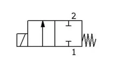
Two-position two-way valve
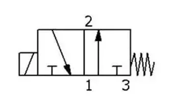
Two-position three-way valve
Two-position three-way valve
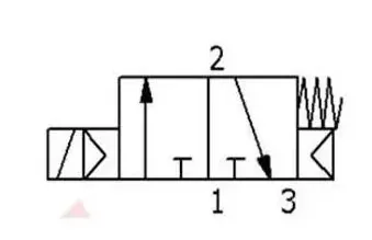
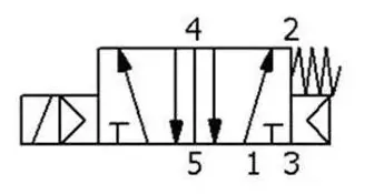
Two-position five-way valve
Conclusion
The graphical symbols used in hydraulic directional valves offer a standardized and efficient way to represent the valve's function, connections, and operating states. By understanding these symbols, engineers and technicians can effectively design, analyze, and maintain hydraulic systems.

