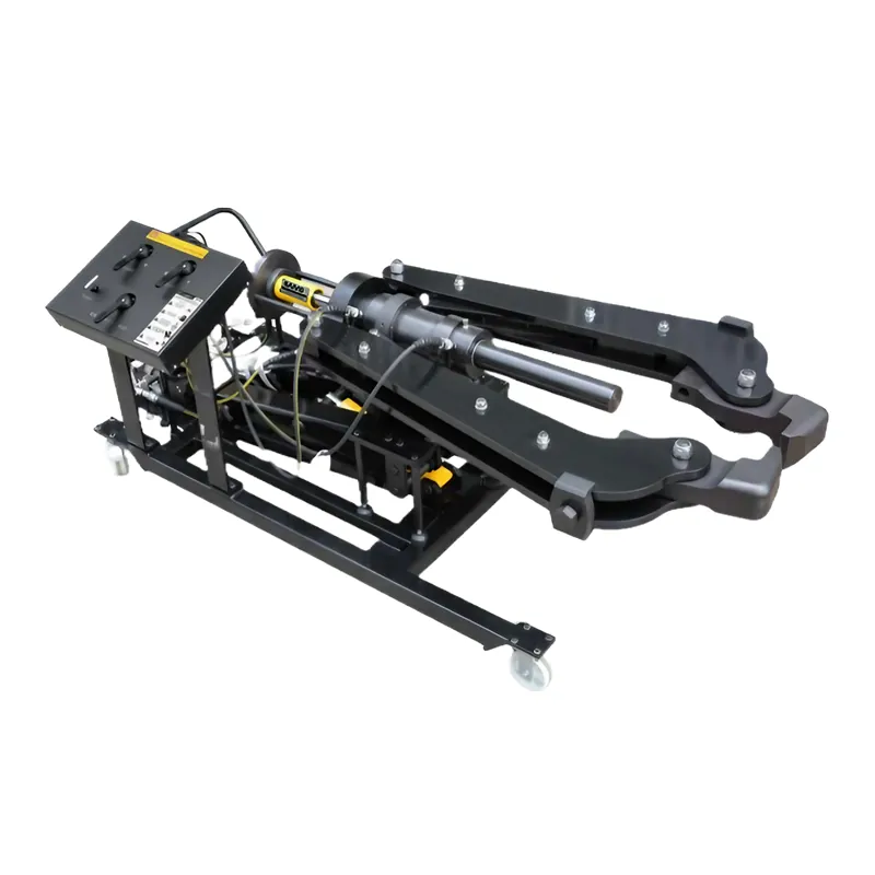
Specific analysis of hydraulic pump station

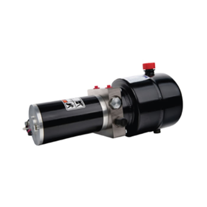
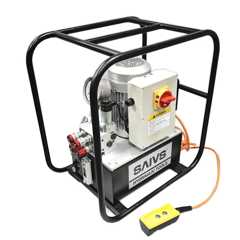
The structural form of the hydraulic station is mainly distinguished by the structural form of the pump unit, installation position and cold-cooling mode.
I. Pump installation can be divided into:
(1) Upper vertical: The pump unit is installed vertically on the tank cover plate, mainly used for the thought of fixed displacement pump system.
(2) Upper horizontal: The pump unit is installed horizontally on the tank cover plate, which is mainly used for variable displacement pump system to facilitate flow regulation.
(3) Bypass type: The pump unit is installed horizontally beside the oil tank on a separate basis. Bypass type can be equipped with standby pump. It is mainly used for systems with large capacity of oil tank 250 litres and power of motor over 7.5 kW.
2. Cooling by station can be divided into:
(1) Natural cooling, but: by the tank itself and air heat exchange cooling, but generally used for systems with tank capacity less than 250 litres.
(2) Forced cooling, but: adopt cooling. cooler for forced cooling. However, generally used for systems with tank capacity greater than 250 litres. The main technical parameters of hydraulic station are oil storage measurement of oil tank and motor power. The tank capacity has 18 specifications (litres/L): 25, 40, 63, 100, 160, 250, 400, 630, 800, 1000, 1250, 1600, 2000, 2500, 3200, 4000, 5000, 6000. According to user requirements and operating conditions, this series of hydraulic stations can be achieved as follows: 1. Configure integrated blocks according to the system or without integrated blocks; 2. Cooler, heater and accumulator can be set; 3 It can be equipped with or without electrical control devices.
3. It can be divided into:
(1) Ordinary steel plate: 5MM-6MM steel plate is used for welding the box and 10-12MM steel plate is used for joining the panel. If there are too many openings, it can be appropriately thickened or reinforced.
(2) Stainless steel plate: 304 stainless steel plate with thickness of 2-3MM is used for the box body, and 304 stainless steel plate with thickness of 3-5MM is used for the panel, and reinforcement is added to the bearing parts.
(3) Internal rust prevention of common steel plate tank is difficult to achieve. Many faults will occur when rust enters oil circulation system. Full stainless steel tank design solves this industry problem.
4. It can be divided into:
(1) Piston type
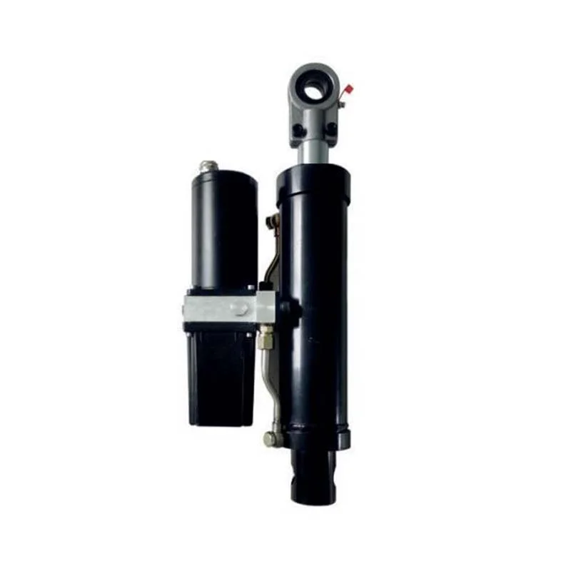
A single piston rod cylinder has a piston rod at only one end. A single-piston Hydraulic Cylinder is shown. Both inlet and outlet ports A and B can pass through pressure oil or return oil to achieve bi-directional movement, so they are called double-acting cylinders.
(2) Piston type
1. The plunger type hydraulic cylinder is a single-acting hydraulic cylinder, which can only move in one direction by hydraulic pressure, and the return stroke of the plunger depends on other external forces or the weight of the plunger.
2. The plunger is supported only by the cylinder liner and does not contact with the cylinder liner, so that the cylinder liner is easy to machine and therefore suitable for long-stroke cylinders.
3. The plunger is always pressurized during operation, so it must have sufficient rigidity;
4.Piston weights tend to be large and sag due to self-weight when placed horizontally, resulting in seal and guide wear on one side, so its vertical use is more advantageous.
(3) Telescopic type
The telescopic cylinder has two or more stages of pistons, the sequence of piston extension in the telescopic cylinder is from large to small, while the sequence of no-load retraction is generally from small to large. The telescopic cylinder can achieve a long stroke, but it has a short length and a compact structure when retracted. Such cylinders are commonly used in construction and agricultural machinery.
4. Oscillating type
The oscillating cylinder is the actuating element that outputs torque and realizes reciprocating motion, also known as the oscillating hydraulic pressure. There are two forms: single-blade and double-blade. The stator block is fixed to the cylinder block and the vanes are connected to the rotor. In accordance with the direction of oil intake, the vanes will drive the rotor to and fro.

