Characteristics and Maintenance of Main Components of Tractor Hydraulic System
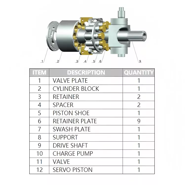
A device that converts mechanical energy into liquid pressure energy and provides pressurized liquid for the tractor Hydraulic System. It belongs to the positive displacement pump, and its basic principle is the volume change of the closed oil cavity. When the volume of the closed oil cavity in the pump expands, it absorbs oil, and when it shrinks, it expels and forces the oil to overcome the resistance and output it to the outside. The volume of oil discharged by the hydraulic pump for one revolution is the displacement. The displacement of the fixed pump is fixed, and the displacement of the variable pump is variable. The oil delivery volume of the hydraulic pump per unit time is the flow rate, and the flow rate is the product of the displacement and the rotational speed of the hydraulic pump.
The product of the pressure difference between the inlet and outlet of the hydraulic pump and the flow rate is the hydraulic power output by the hydraulic pump.

Hydraulic pumps can be divided into gear pumps, rotor pumps, Vane Pumps and plunger pumps according to their structure.
The tractor hydraulic system is an important power source for farm implement operations. With the sharp increase in the number of rural tractors, understanding the technical characteristics of the main components of the tractor hydraulic system and using the hydraulic system correctly is an effective guarantee to reduce the failure of the tractor hydraulic system and improve productivity.
1 Technical characteristics of the main components of the hydraulic system
The tractor hydraulic system consists of plunger oil pump, control valve, oil cylinder and safety valve, and oil tank. Let us take the hydraulic system of a small tractor as an example to talk about the technical characteristics of the main components of the hydraulic system.
(1) Plunger oil pump. The plunger oil pump is mainly composed of pump body, plunger, plunger spring, eccentric wheel, steel ball and one-way valve. This single plunger pump is easy to process and reliable to use. Since the control valve and safety valve are also installed on the pump body, it has a compact structure and less oil leakage. The entire oil pump and control valve are fixed to the gearbox front cover with 3 bolts. There is an eccentric wheel on the I-axis of the gearbox, which is equipped with a 108 ball bearing, and the plunger spring keeps the plunger in contact with the 108 ball bearing all the time. There is a ring groove in the middle of the plunger, which is communicated with the oil inlet and the oil return port, and a radial through hole is drilled in the groove, which is communicated with the axial hole in the center of the plunger, thereby forming the oil inlet of the oil pump. A steel ball is installed above the axial hole (it acts as a check valve when the oil is pressed). In order to limit the height of the steel ball during the oil suction stroke of the plunger, a stop pin is installed above the steel ball. There is a one-way valve above the plunger, which consists of a one-way valve body, a one-way valve spring and a one-way valve screw cover. It is a one-way oil outlet valve, which is used to control the oil chamber of the plunger pump and the high-pressure oil circuit. The one-way valve opens when the plunger supplies oil, and closes when it absorbs oil.
The working process of the plunger oil pump: when the oil pump clutch handle is placed in the "closed" position, the oil pump works, and the plunger reciprocates under the action of the eccentric wheel and the spring force of the plunger. When the lift of the eccentric decreases (the radius gradually decreases during the rotation), the plunger moves downward under the action of the spring force of the plunger, the volume of the pump oil chamber at the top of the plunger increases, the pressure decreases, and the one-way valve is in Under the action of the spring force, the oil passage leading to the control valve is closed, and the oil in the oil tank lifts the steel ball that closes the axial oil hole of the plunger through the oil inlet passage, and flows into the pump oil cavity at the top of the plunger. When the lift of the eccentric wheel increases (the radius gradually increases during the rotation), the plunger moves upward to compress the plunger spring. At this time, the steel ball closes the axial hole of the plunger under the action of its own weight and upper oil pressure. Close the oil inlet. As the volume of the pump oil chamber decreases, the pressure of the oil rises rapidly, and the oil top opens the check valve into the oil cylinder or flows back to the oil tank. Therefore, the I-axis of the gearbox rotates once, and the plunger moves up and down once to complete the whole process of oil absorption and oil pressure.
(2) Safety valve. The safety valve is installed on an oil channel parallel to the main oil channel on the side of the oil pump to limit the maximum working pressure of the hydraulic system to protect the parts from damage. Under normal circumstances, the opening pressure of the safety valve is 12 ± 1 MPa. When the oil pressure exceeds this value, the oil will open the safety valve steel ball and flow back to the oil tank.
(3) Control valve. The control valve of the small tractor is a rotary valve type directional control valve, which is used to control the flow direction of the oil. It has 3 positions of lifting, neutral and lowering, which can make the farm implement lift, maintain a certain height and lower three working conditions. The control valve is installed in the seat hole on one side of the pump body. The valve core has a special cross-sectional shape, forming two arc grooves and two flanges, and the valve core is also drilled with a radial hole and an axial hole.
(4) Oil cylinder. The Hydraulic Cylinder is installed in the oil tank and consists of a cylinder block, a piston, a piston rod, a drain valve and a limit plate. Two O-shaped oil-resistant rubber sealing rings are installed in the annular groove of the piston to seal the fitting clearance between the oil cylinder and the piston. One end of the piston rod is connected to the piston by a blank pin, and the other end is connected to the inner lift arm by a pin. The oil inlet hole of the oil cylinder and the oil outlet of the control valve are connected by oil pipes. A drain valve is installed on the piston of the oil cylinder, and its main function is to limit the maximum lifting height of the agricultural implement to prevent the piston from protruding too much from the cylinder, causing the inner lift arm to burst the oil tank. Under the action of the spring, the oil drain valve is sealed with the oil drain hole on the piston with a "ring belt fit" to prevent the hydraulic oil in the oil cylinder from leaking. When hydraulic oil from the plunger oil pump enters the cylinder, it pushes the piston to move backwards. The inner lifting arm is pushed by the piston rod to rotate, and the suspension mechanism is driven to lift the agricultural implement. When the rear end of the drain valve hits the limit plate, the drain valve spring is compressed. There is a gap between the ring belt matched with the oil drain valve and the oil drain hole, the hydraulic oil flows back to the oil tank from the gap, the piston stops moving, and the agricultural implement rises to the highest position.
(5) Fuel tank. The fuel tank is composed of the rear cover, the bottom plate of the rear cover and the refueling vent plug. It is fixed above the rear of the gearbox housing and replaces the rear axle cover. A refueling vent plug is installed on the rear and upper part of the fuel tank, which keeps the tank connected to the atmosphere at all times, ensuring that the pressure above the liquid level is always equal to the atmospheric pressure, so as to prevent the pressure in the tank from changing when the oil temperature changes and affecting the oil supply. Unscrew the refueling vent plug to add hydraulic oil to the oil tank.
(6) Locking device. When the tractor-mounted farm implements travel for a long distance, it is necessary to lift the farm implement to the highest position. In order to reduce the power consumption of the engine and the wear of the plunger oil pump, the plunger oil pump can be separated at this time to stop the oil pump. In order to prevent the agricultural implement from falling under its own weight while driving, a locking device is installed at the lower part of the rear of the fuel tank. When the control handle is pulled forward to the vertical position, the inner lifting arm is in a mechanical locking state, which can reliably fix the suspended farm implement at the highest position and ensure the safe driving of the unit.
2 Main points of use and maintenance of hydraulic system
(1) During the maintenance of each shift, the oil level of the fuel tank and the reliability of the hydraulic system seal should be checked, and there should be no oil leakage. Precision parts such as hydraulic pumps, control valves and Hydraulic Cylinders have been adjusted before leaving the factory. Generally, they should not be adjusted in use. During use, the opening pressure of the safety valve of the hydraulic system cannot be arbitrarily increased, so as not to cause the gear oil pump, distributor, multi-way reversing valve housing and oil pipe to burst.
(2) When replacing hydraulic oil, pay attention to the following matters: First, turn off the engine and release the oil in the oil tank and hydraulic system parts while it is hot. The second is to add the cleaned diesel oil to the oil tank of the hydraulic system, start the engine, and use the suspension mechanism to lift it 4 to 5 times (to make the hydraulic system work reciprocatingly). The third is to turn off the engine and release the cleaned diesel oil from the fuel tank, distributor and cylinder respectively. Fourth, take out the filter in the hydraulic oil tank and clean it with diesel oil.
(3) In the hydraulic system, the inlet and outlet of the oil passage and the orifice of the positioning pin are equipped with O-ring seals. Be careful not to lose them during disassembly and assembly. If the seal ring is damaged, it should be replaced.

